ESP8266 is cost effective end point transceiver for your embedded application which facilitates you IOT application to connect with server side interface using HTTP protocol. To control any IOT / Embedded application you can connect ESP8266 Wifi Module with your micro controller which sends and receives instructions through Internet and on behalf of communication micro controller can decide output and act accordingly.
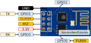
ESP8266 contains 8 pins as mentioned below.
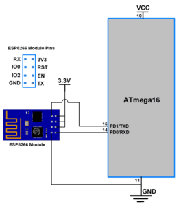
Interfacing of ESP8266 WiFi module with Atmega32
Note: ESP8266 is compatible on 3.3V connecting same with 5V power source may damage or crash its firmware.
- Connect GND with GND.
- Connect TX with Microcontroller’s RX pin.
- Connect RX with Microcontroller’s TX pin.
- Connect EN, RST and VCC with 3.3V power source.
- Leave GPIO 0 and GPIO2 as it is.
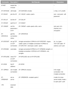
ESP8266 requires set of AT commands to configure this with wifi network and pair with your micro controller.
Sample Program.
#define F_CPU 8000000UL
#include <avr/io.h>
#include <util/delay.h>
#include <stdlib.h>
#include <stdio.h>

//#define USART_BAUDRATE 9600
#define BAUD_PRESCALE (((F_CPU / (USART_BAUDRATE * 16UL))) - 1)


void UART_init(long USART_BAUDRATE)
{
	UCSRB |= (1 << RXEN) | (1 << TXEN);/* Turn on transmission and reception */
	UCSRC |= (1 << URSEL) | (1 << UCSZ0) | (1 << UCSZ1);/* Use 8-bit character sizes */
	UBRRL = BAUD_PRESCALE;		/* Load lower 8-bits of the baud rate value */
	UBRRH = (BAUD_PRESCALE >> 8);	/* Load upper 8-bits*/
}

unsigned char UART_RxChar()
{
	while ((UCSRA & (1 << RXC)) == 0);/* Wait till data is received */
	return(UDR);			/* Return the byte*/
}

void UART_TxChar(char ch)
{
	while (! (UCSRA & (1<<UDRE)));	/* Wait for empty transmit buffer*/
	UDR = ch ;
}

void UART_SendString(char *str)
{
	unsigned char j=0;

	while (str[j]!=0)		/* Send string till null */
	{
		UART_TxChar(str[j]);
		j++;
	}
}

int main()
{
	char c;
	UART_init(9600);

	UART_SendString("\n\t Echo Test ");
	while(1)
	{
		c=UART_RxChar();
		UART_TxChar(c);
	}
}


